
When planning a traffic signal installation, specifying the correct signal head mounting positions is just as important as selecting the appropriate traffic signal pole. The position of each signal head affects driver visibility, lane guidance, intersection safety, and the overall layout of the signal system. For traffic engineering contractors, municipal authorities, and equipment buyers, clearly defining these positions before production can help reduce installation difficulties and avoid unnecessary modifications on site.
A well-prepared mounting specification should describe not only where each signal head will be installed, but also its height, orientation, horizontal reach, and relationship to the traffic lanes it controls.
1. Identify the Traffic Movement Controlled by Each Signal Head
The first step is to establish which traffic movement each signal head is intended to control. Through traffic, left-turn traffic, right-turn traffic, and pedestrian movements may require different signal arrangements depending on the intersection design.
For example, a signal head controlling a dedicated left-turn lane should be positioned so that drivers in that lane can identify the relevant indication without confusing it with signals for adjacent movements. At intersections with multiple approach lanes, the mounting plan should clearly identify the intended lane or movement for every signal head.
Project drawings should include lane markings, stop lines, medians, and the direction of approaching traffic. These details allow the pole designer to understand the required signal positions and determine whether a vertical pole, single cantilever arm, or double cantilever arrangement is appropriate.
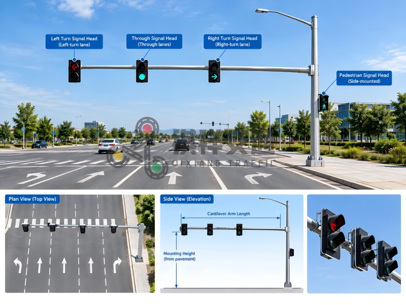
2. Choose Between Vertical Pole and Cantilever Mounting
The mounting configuration should be selected according to roadway width, available roadside space, and the required viewing positions.
A vertical pole with side-mounted signal heads may be suitable for narrower roads or locations where signals can be positioned near the roadside without compromising visibility. A cantilever pole is often considered for wider roads, multilane intersections, and locations where signal heads need to extend over specific lanes.
For cantilever installations, the horizontal arm length is a critical specification. It should be determined from the required signal head coordinates rather than selected solely according to the overall roadway width. The position of the pole foundation, the distance from the curb, the lane layout, and the mounting hardware all influence the final reach.
If several signal heads are installed on one arm, their spacing should be defined individually. This helps prevent conflicts between signal housings, mounting brackets, and other equipment.
3. Specify Mounting Height and Roadway Clearance
Mounting height should be measured from a clearly identified reference level, such as the finished pavement or the relevant sidewalk grade. The specification should also state whether the dimension refers to the bottom of the signal housing, its centerline, or another reference point.
This distinction matters because the signal housing, bracket, visor, and any additional attachments may occupy different vertical positions. A drawing that provides only the pole height does not necessarily establish the actual mounting height of the signal head.
Requirements vary according to the country, road classification, and installation type. For example, the U.S. Manual on Uniform Traffic Control Devices (MUTCD), 11th Edition, Section 4D.09, specifies a minimum height of 15 feet from the pavement to the bottom of a vehicular signal housing and its related attachments when the signal face is located over a portion of the highway used by motor vehicles. Different provisions apply to signal faces mounted outside the roadway.
These figures should not be applied automatically to projects in other countries. The applicable local traffic regulations, vehicle clearance requirements, and approved project drawings should determine the final dimensions.
4. Define Signal Orientation and Viewing Angles
Correct mounting coordinates alone cannot guarantee that drivers will see the intended signal clearly. Each signal head must also face the appropriate approach.
The orientation specification should identify the direction of approaching traffic and, where necessary, the intended horizontal and vertical aiming angles. Road curves, uphill or downhill approaches, wide intersections, and nearby structures can affect the driver’s viewing angle.
Designers should check whether trees, buildings, overhead signs, utility equipment, or other signal heads could obstruct the required field of view. They should also consider whether the signal indication could be mistaken for a signal controlling another approach.
Where the intersection geometry creates unusual viewing conditions, the engineer may need to adjust the signal head orientation or consider supplementary signal faces. Final positioning should follow the applicable traffic control standards and the approved traffic engineering design.
5. Provide Exact Mounting Coordinates and Bracket Details
To avoid ambiguity during manufacturing, the mounting schedule should provide measurable reference points rather than relying on descriptions such as “high on the pole” or “near the end of the arm.”
A useful schedule can include:
Signal head identification number and controlled movement
Mounting structure and arm location
Horizontal distance from a defined pole or arm reference point
Vertical mounting height and measurement datum
Signal head orientation and aiming direction
Bracket type, attachment method, and required spacing
Housing dimensions, weight, and any relevant accessory requirements
For projects with several signal heads, each position should be marked on the elevation and plan views. The drawings should also show how the mounting brackets connect to the pole or cantilever arm.
Signal head weight, wind loading, arm reach, and the arrangement of multiple attachments should be considered during structural design. The pole and its connections must be suitable for the loads specified by the project engineer.
6. Check Installation, Wiring, and Maintenance Access
Signal head positions should be practical not only for traffic visibility but also for installation and future maintenance.
Mounting arrangements must leave sufficient space for electrical connections, cable routing, junction boxes, and other specified equipment. Cable entry points should be coordinated with the pole design so that installers do not need to drill unapproved openings or modify structural components on site.
Maintenance personnel should be able to access the signal heads using the intended maintenance method. Adjacent heads and brackets should not create unnecessary interference during inspection, replacement, or adjustment.
Before finalizing the drawings, the project team should review the proposed layout against nearby streetlights, road signs, overhead utilities, and other roadside infrastructure.
7. Confirm the Mounting Layout Before Production
A final drawing review is an effective way to identify inconsistencies before the traffic signal pole enters production. Contractors and buyers should verify that the number of signal heads, arm lengths, mounting heights, bracket positions, and orientation requirements match the approved intersection layout.
Any changes to lane arrangements or signal head positions should be reflected in the latest drawing revision. Verbal instructions alone may lead to misunderstandings between the project designer, pole manufacturer, and installation team.
For custom traffic signal poles, providing dimensioned drawings, signal head specifications, and clear installation requirements helps the manufacturer prepare the appropriate pole configuration and mounting accessories.
Conclusion
Specifying signal head mounting positions requires coordination between traffic engineering, pole design, equipment selection, and field installation. Lane assignment, mounting configuration, vertical clearance, viewing angles, attachment details, and maintenance access should all be addressed before production begins.
For traffic signal projects involving custom poles or multiple signal heads, a complete and dimensioned mounting schedule can make the design easier to review and the installation easier to execute. By confirming these details early, project teams can improve coordination, reduce avoidable site modifications, and ensure that the manufactured structure matches the intended traffic control layout.
Post time: Oct-16-2026


